
Residual current devices (RCDs) are arguably the most important electrical safety devices for human beings in both residential and industrial settings. Where circuit breakers function to protect electronic devices and electrical systems from electrical overload, the residual current device is designed to cut the flow of electricity to your circuit when it detects that the flow of electricity is going to travel down an unwanted path. The speed at which the RCD cuts the electrical flow varies from 40 to 300 milliseconds after the detection of a fault. They are not failproof, however, and many factors influence the speed of response. This article examines the simulation of an RCD to determine the factors that affect its response times.
Ensuring the safety of users around electrical contacts
In both the civil and industrial fields, safety is non-negotiable in installations, but how exactly are we protected from electrical contacts? When we receive an electric shock, a portion of the current disperses from the system to the ground, passing through our bodies.
This portion of the current, called “differential”, is detected by appropriate systems (electrical, electronic) that trigger, by means of residual current devices (RCD), the breakers that power the system. Generally, an RCD is composed of a detection unit (electric, electronic) and an actuator (trip) that triggers the mechanical disconnection or “trip” of the power breaker.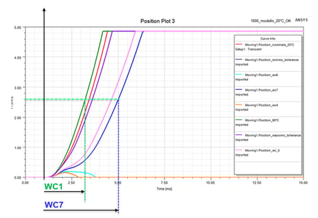
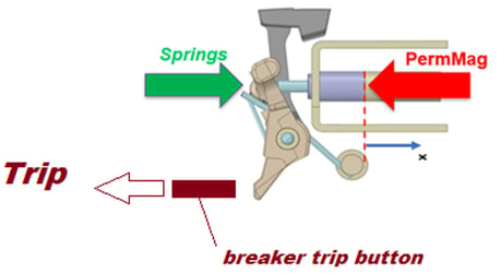
An RCD-trip switch (shown in the figure) activates the release button of the circuit breaker by means of a switch-lever that is operated by a loaded flexural spring held in static equilibrium by a permanent magnetic circuit. Once the trip is triggered, an electrical discharge from the capacitor powers a solenoid that depolarizes the magnetic circuit, allowing the switch-lever to move. Since it is equally governed by electromagnetic and mechanical phenomena, an RCD-trip is considered to be a Multi-physical system.

A preliminary analysis was conducted with Cetol6σ in order to identify the construction factors of greatest functional influence and to generate a scale of sensitivity for the geometric and 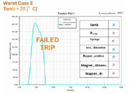 dimensional elements on the drawings. The RCD’s kinematic nature is clearly a 1 degree-of-failure (DoF) system, which was studied with RecurDyn based on rigid-body modeling. The aim of this part of the study was to obtain the laws of total force (elastic-friction) and of equivalent mass, both of which were transposed to the translational free coordinate of the plunger, which coincided with the magnetic gap used in the final studies with Ansys Maxwell.
Ansys Maxwell simulation software for electromagnetic fields is used to design and analyze 2- and 3-D electromagnetic and electromechanical devices, including motors, actuators, transformers, sensors and coils. It uses the finite element method to solve static, frequency-domain, and time-varying electromagnetic and electric fields.
One of its key benefits is its automated solution process, which only requires the user to specify the geometry, the material properties and the desired output, after which Maxwell automatically generates an appropriate, efficient and accurate mesh for solving the problem.
The analyses with Maxwell resolved the coupled equations between the dynamic and electromagnetic fields, which enabled the governing laws in the coil, the magnetic field and the induction in space, position and speed of the plunger to be obtained.
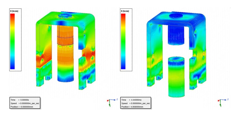
There are considerable differences in the RCD’s performance depending on the set of physical-geometric factors permuted according to the possible worst-case scenarios. We note that the RCD’s response time can double depending on the specific worst case, just as it can even fail if the upper limits of dimensional and flowmetric tolerance for iron and magnets are not contained. This result is in accordance with what can be observed from the working point on curves B_H, which highlight the “saturation” of the magnetic circuit (and consequently a marked increase in the forces antagonistic to the motion, in proportion to the iron and magnets).
